

Panic Bar Installation Guide for Commercial Doors

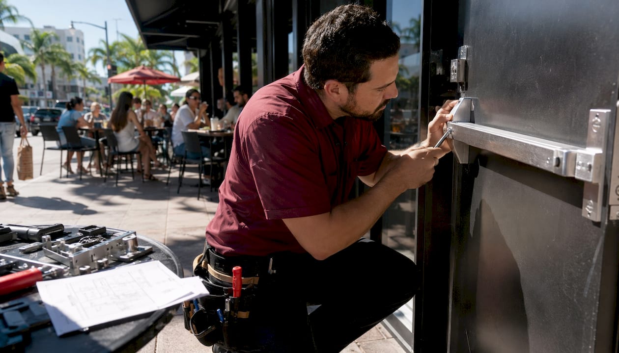
You can install a code-compliant panic bar yourself on most standard doors if you match the device type to the door, follow the manufacturer’s template precisely, and avoid any wiring work on electrified models. Improperly installed panic hardware risks failed fire inspections and serious liability. If your door is electrified, part of a fire-alarm system, or you’re unsure about frame reinforcement, stop and call a licensed locksmith.
Quick-step overview:
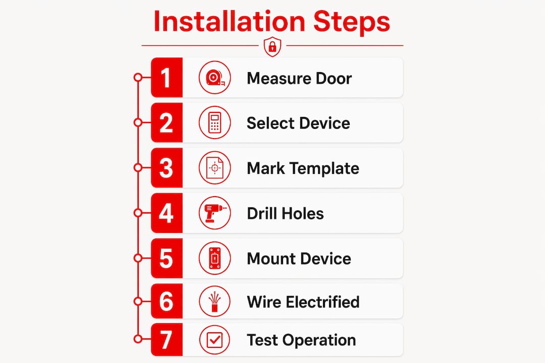
Measure the door width, thickness, and height from the finished floor
Apply the template from the manufacturer and mark all hole locations
Drill mounting holes and the latch case cutout (if required by device type)
Mount the chassis and brackets using through-bolts or frame-appropriate fasteners
Install the strike plate and align it to the latch
Test pushbar actuation, door close/latch, and release force
Safety callout: Panic hardware is life-safety equipment. The pushbar must release with no more than 15 pounds of pressure on the touchpad — a critical compliance target in the U.S. Electrified devices require AHJ coordination and should be treated as both electrical and life-safety work.
Pro Tip: If the device is electrified, the door frame material is unknown, or the first operation test fails, call a licensed locksmith before proceeding. Life-safety hardware is not the place to troubleshoot blind.
Table of Contents
What type of panic device does your door actually need?
Matching the hardware family to your door is the single most critical decision in the whole process. Using the wrong device family leads to mechanical failure or noncompliance, regardless of how carefully you drill.
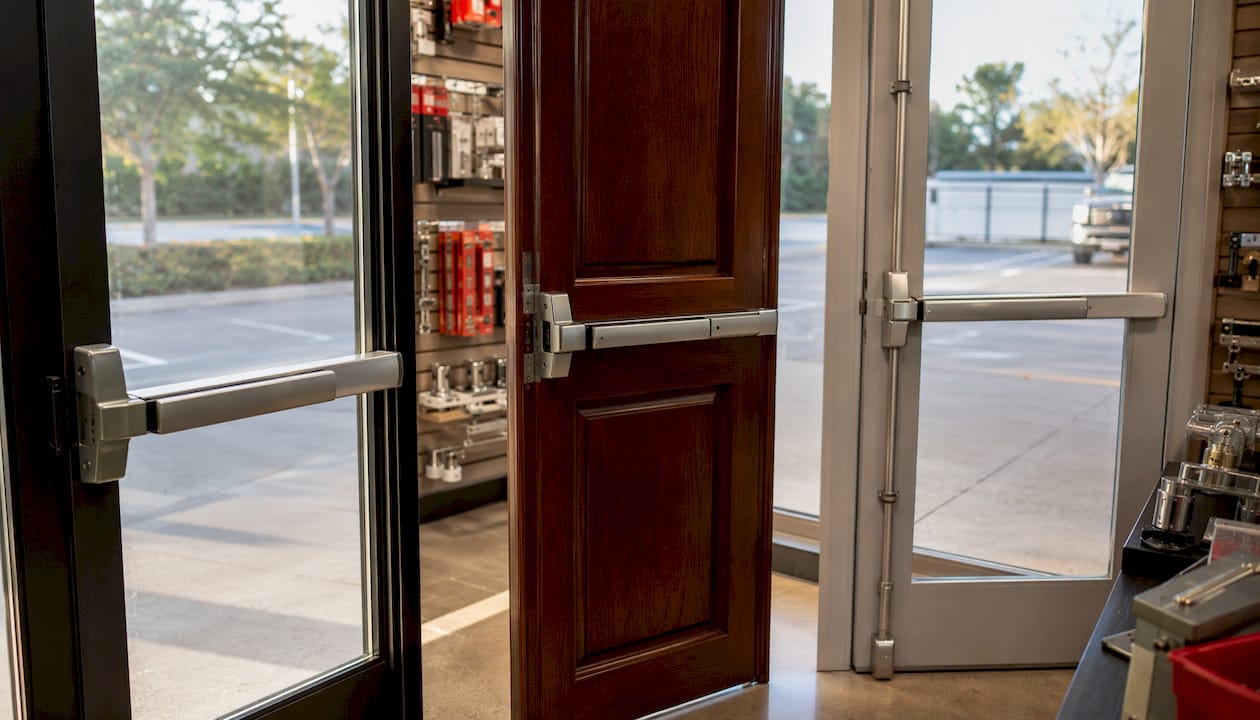
Rim (surface-mounted) devices are the most common choice for hollow metal and wood doors. The latch case mounts directly to the door face, and the strike mounts to the frame. Installation is relatively straightforward, and these devices work well on single-door applications with standard frame conditions.
Mortise exit devices require a mortise pocket cut into the door edge. They offer a more integrated look and stronger latching, but the pocket must be precisely routed and the door must have sufficient edge thickness. These are common on heavier commercial doors where a flush profile matters.
Vertical-rod devices (surface or flush) extend rods up and down from the pushbar to top and bottom strikes. They’re the go-to solution for double doors, glass aluminum storefront doors, and any door where a rim latch at the edge isn’t practical. Surface vertical-rod models are easier to install; concealed (flush) rod versions require routing channels inside the door.
Touchbar-style non-latching exit switches don’t latch the door at all. They’re used where the door is held closed by a magnetic lock or another electrified device, and the touchbar simply signals a Request-to-Exit (REX) to release the mag lock.
Device Type | Best Door Match | Common Challenge | Typical Use Case |
Rim (surface) | Hollow metal, wood | Strike alignment on uneven frames | Single commercial or residential door |
Mortise | Heavy steel, solid wood | Precise pocket routing required | High-traffic commercial entry |
Surface vertical rod | Double doors, aluminum storefront | Rod travel adjustment, top/bottom strike alignment | Pairs of doors, glass storefront |
Flush vertical rod | Double doors, wood pairs | Routing channels inside door stiles | Upscale commercial, wood double doors |
Non-latching touchbar (REX) | Any door with mag lock | Requires access-control integration | Access-controlled entries |
Pro Tip: Before buying hardware, measure the door edge thickness and check for a reinforcement plate. Aluminum storefront doors often need shims or a special narrow-stile bracket. Ordering the wrong backset or chassis width is the most common and most expensive mistake.
Tools and materials you need before you start
Showing up without the right tools means stopping mid-job. Gather everything below before you touch the door.
Tools:
Variable-speed drill with a full set of twist bits
Hole saw or knockout punch (for latch case cutouts and wiring access)
Center punch and hammer (for accurate hole starts on metal)
Metal miter saw or hacksaw (for field-cutting rails to door width)
Torque screwdriver or driver with torque settings
Level (4-inch and 24-inch)
Tape measure and pencil or scribe
Safety glasses and work gloves
Materials and fasteners:
Manufacturer-supplied template (never substitute a generic one)
Through-bolts and sex nuts/blind nuts for hollow metal doors
Wood screws with appropriate pilot holes for wood doors
Shims for narrow aluminum stile doors
Strike plate and frame fasteners matched to frame material
Weatherstripping (if replacing an existing device on an exterior door)
Conduit fittings and armored cord (electrified models only)
Always use the device template and keep the manufacturer’s manual on-site throughout the job. Generic procedures without the model-specific template result in mis-drilled holes and failed operation. No exceptions.
Pro Tip: Buy two extra through-bolts and a spare strike plate before you start. Stripped threads on a hollow metal door mid-install are a real problem, and hardware stores rarely stock commercial-grade sex nuts.
Step-by-step installation for rim, mortise, and vertical-rod devices
The high-level sequence applies to every device type: measure, apply template, mark, drill, mount chassis, install fasteners, cut rails if required, install strike(s), adjust, and test. What changes is the detail at each step.
Rim device installation
Tape the manufacturer’s template to the door at the correct height (pushbar centerline between 34 and 48 inches above the finished floor).
Use a center punch to mark every hole location through the template.
Drill pilot holes first, then open to the specified diameter. For hollow metal doors, use a sharp step bit or twist bit and back the door skin with a scrap block to prevent blowout.
If the device requires a latch case cutout on the door edge, use a hole saw or chisel to the template dimensions.
Feed through-bolts through the door and thread sex nuts from the back. Leave fasteners slightly loose at this stage.
Position the chassis, check level, and confirm the latch aligns with the door edge. Then tighten fasteners progressively, not all at once.
Install the exterior trim and backing plate if included.
Mount the strike to the frame. Strike misalignment by as little as 1/8 inch can prevent proper latching or cause binding. Use frame-appropriate fasteners.
Test operation before final torque.
Mortise device installation
Verify the door edge is thick enough for the mortise pocket before ordering the device. Mark the pocket location from the template, then rout or chisel to the exact depth specified. Seat the mortise case fully before drilling through-bolt or tapped-hole locations. Confirm the reinforcement plate (if present) doesn’t interfere with the pocket depth. Reassemble and check that the latch extends and retracts cleanly before mounting the pushbar chassis.
Vertical-rod device installation
Attach the pushbar chassis to the door face using the same template-and-through-bolt method as a rim device. Then attach the top and bottom rod assemblies. Field-cutting rails to door width is standard practice. Use a metal miter saw for a square, clean cut. A badly cut end interferes with the end cap bracket and can jam the mechanism. Install top and bottom keepers/strikes in the frame header and threshold, then adjust rod travel so both engage simultaneously when the pushbar is released.
Special notes:
Double doors: prepare the inactive leaf first (flush bolts or coordinator), then install the active-leaf device
Dogging feature: confirm the dogging hex key or cylinder is accessible after installation
Removing an existing device: back out through-bolts completely, support the device so it doesn’t drop and damage the door edge, then remove the strike before the chassis
Operation checklist after mounting:
Push the bar at the center, then at each end — latch should retract fully each time
Release the bar and confirm the door latches under gravity (no manual push needed)
Check for binding or drag along the full door swing arc
Verify the dogging feature (if present) holds the bar in the retracted position
Pro Tip: Keep all fasteners slightly loose until you’ve confirmed the latch aligns with the strike and the bar moves freely. Overtightening before alignment is the most common cause of binding that’s hard to correct later.
How to wire and power an electrified panic bar
Electrified installs add wiring and AHJ coordination to every step. Treat them as electrical and life-safety work from the start, not an afterthought.
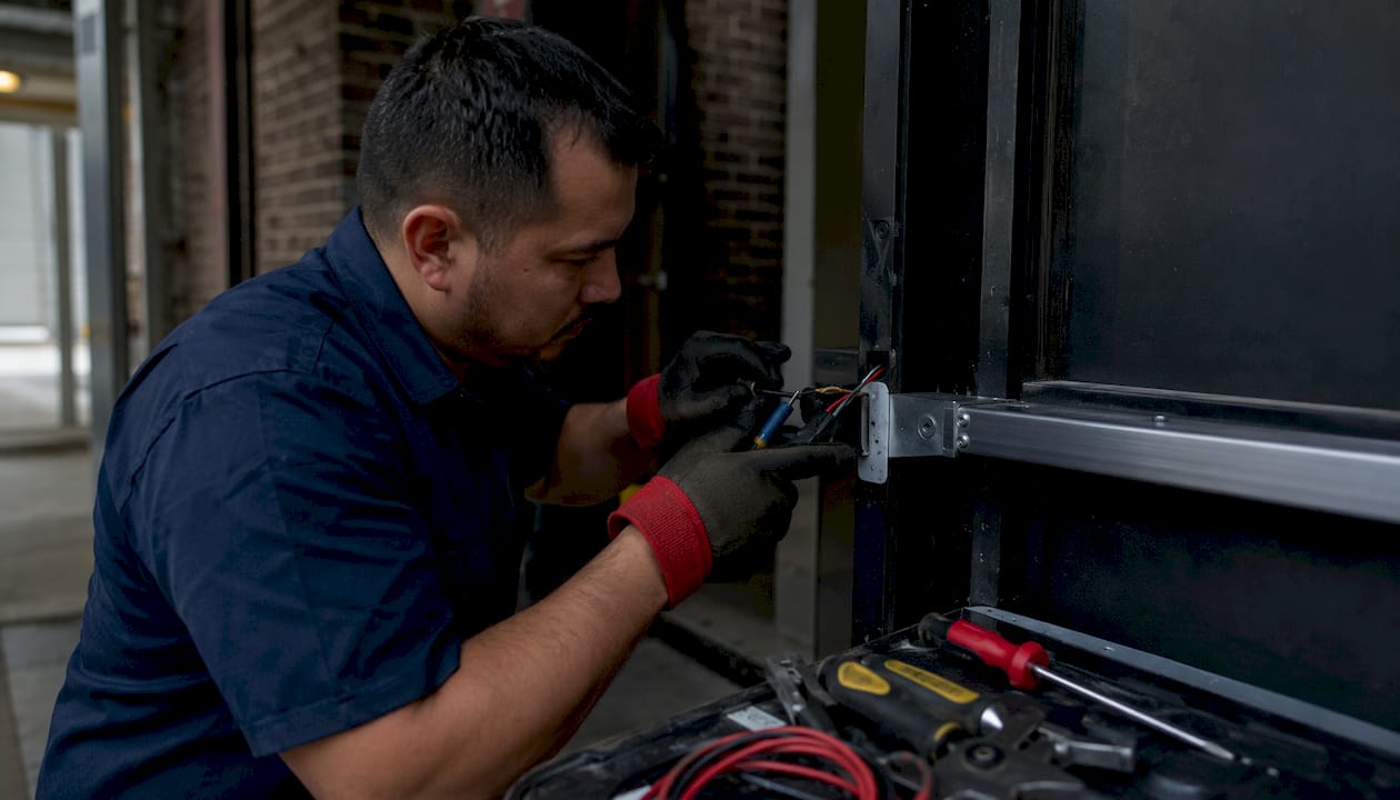
Power transfer methods
Three methods carry power from the frame to the door:
Electric hinge: Power runs through a modified hinge barrel. Clean installation, minimal visible hardware, but requires a compatible hinge cutout and careful wire routing inside the door.
Armored door cord (loop): A flexible armored cable loops from the frame to the door. Easier to retrofit, visible but durable. This is the preferred method for most field installs.
Power transfer device (PTD): A dedicated transfer unit mounts at the hinge edge. More reliable than a cord for high-cycle doors, but requires precise alignment.
The Schlage 672 Series TouchBar ships with a 24-inch pre-connected cable on some configurations and specifies exact hole sizes and locations for wiring access. Follow those dimensions. Drilling through the door face without backing compromises the door skin and can void the device warranty.
Wiring path and access-control integration
Route wiring through the door using only the manufacturer-specified hole locations. Use conduit or armored cord where the wire is exposed. Connect the electrified latch or solenoid to your access-control panel following the wiring diagram in the manual.
REX switch vs. non-latching touchbar: A REX switch signals the access-control panel to release a mag lock when someone pushes the bar. A non-latching touchbar does the same thing mechanically, with no latch to retract.
Mag lock integration: The fire alarm system must be wired to release the mag lock on activation. Confirm this with the AHJ before final connection.
Fail-safe vs. fail-secure: Most life-safety exit devices are fail-safe (power loss = door unlocked). Never override this function.
Wiring safety: Lock out power to the access-control panel before connecting any wires. Follow the manufacturer’s wiring diagram exactly. Electrified models often require AHJ approval for integration with fire or access systems — coordinate with local authorities early, not after the device is mounted.
Pro Tip: Prefer a routed armored cord or the factory AR (armored) option over a bare wire loop. Test the REX output under load before final assembly. A REX that works on the bench but fails under door pressure is a common callback.
How to test, troubleshoot, and maintain your exit device
A device that passes a bench test but fails under real door conditions is a liability. Run every check below before calling the job complete.
Operation test checklist:
Push the bar at the center, left end, and right end — latch must retract fully at all three points
Close the door and confirm it latches without manual assistance
Verify the door opens freely from the push side with no more than 15 pounds of force on the pushpad, which is the industry standard for life-safety compliance in the U.S.
Test the dogging feature (if present): bar should hold retracted and release cleanly
For electrified devices: verify the REX output triggers the access-control release and the door opens
Troubleshooting common problems:
Stiff or binding action: Check chassis alignment first. Loosen fasteners slightly and re-center the device. Over-tightening before alignment is the usual cause.
Latch not engaging the strike: Measure the gap between latch and strike. Even 1/8-inch misalignment prevents proper latching. Loosen the strike, shift it, and re-tighten.
Rattle or noise: Check for loose through-bolts or a shim that has shifted. Tighten fasteners to the manufacturer’s torque spec.
Electrical failure: Check the power transfer connection first, then the wiring at the solenoid. A loose armored cord connector is the most common cause.
Maintenance schedule:
Quarterly (heavy-traffic doors): check fastener torque, test pushbar force, inspect rod travel on vertical-rod devices
Annually: lubricate pivot points and latch mechanism with a dry lubricant (avoid oil-based products that attract debris), verify strike alignment, and inspect weatherstripping
After any door adjustment: re-test full operation and re-verify strike alignment
When a test reveals a life-safety failure, tag the door out of service immediately and call a licensed locksmith. Document the issue and keep the record with the manufacturer’s instructions.
U.S. code basics, ADA requirements, and liability risks
Panic hardware is required by building and fire codes for high-occupancy and assembly spaces in the U.S. OSHA 1910.36 and the IBC Section 1010.2.9 both address exit door hardware requirements for means of egress. Getting this wrong isn’t just a failed inspection — it’s a life-safety risk.
Key figures: The pushpad must release with no more than 15 pounds of force. The pushbar centerline should be positioned between 34 and 48 inches above the finished floor to meet ADA ergonomic ranges.
Compliance checklist:
Confirm the occupant load for the space — panic hardware thresholds vary by occupancy type
Verify door swing direction (must swing in the direction of egress travel)
Check whether a mag lock or delayed-egress device changes the hardware requirements
Confirm ADA height compliance for the pushbar centerline
For electrified devices: contact the AHJ before installation and ask about permit and inspection requirements
Liability is real. Improperly installed panic hardware can cause failed fire inspections and expose building owners to serious legal risk. Keep the manufacturer’s instructions and your installation records on-site and accessible to inspectors. If you’re unsure whether your jurisdiction requires a permit for this work, call the AHJ before you drill a single hole.
When should you hire a professional locksmith?
Some installations are straightforward enough for a competent DIYer or facilities manager. Others require a licensed locksmith or electrician. Know which situation you’re in before you start.
Hire a professional when:
The device is electrified and integrates with a fire alarm or access-control system
The door frame material or reinforcement condition is unknown
The install involves a complex double-door or concealed vertical-rod configuration
Any operation test fails and you can’t identify the cause
The AHJ requires a permit or inspection for the work
You’re replacing hardware on a door with an occupant load that triggers code requirements
What a professional will do on-site:
Verify door and frame compatibility before ordering hardware
Install reinforcement plates if the frame can’t support through-bolts
Wire power-transfer devices and test REX output under load
Perform a full operational test and document results
Provide paperwork for the AHJ or inspector
Questions to ask before booking:
Are you licensed and insured for commercial door hardware in Florida?
Have you installed this device family before (rim, mortise, vertical rod)?
Do you provide documentation for AHJ inspections?
What’s your warranty on the installation labor?
Before the technician arrives: clear the work area around the door, have the device and manufacturer template on-site, and prepare a list of all doors with their dimensions and frame types. That prep time saves you money on the service call.
Locksmithfromiami handles commercial lock installation across Miami and Homestead, including exit device work on both standard and electrified doors. For urgent needs, the team is available around the clock.
Key Takeaways
Proper panic bar installation requires matching the device to the door, using the manufacturer’s template, and verifying operation before the job is done.
Point | Details |
Match device to door first | Rim, mortise, and vertical-rod devices each suit different door types; wrong family = mechanical failure. |
Template use is mandatory | Generic procedures without the model-specific template cause mis-drilled holes and failed operation. |
15-pound activation standard | The pushbar must release with no more than 15 pounds of force to meet U.S. life-safety compliance. |
Electrified installs need AHJ coordination | Wiring and fire-alarm integration require AHJ approval; hire a licensed locksmith for this work. |
Locksmithfromiami for professional installs | Locksmithfromiami provides code-aware exit device installation in Miami and Homestead, available 24/7. |
Why professional installation matters more than most guides admit
Most how-to guides on panic bar installation treat the job as a straightforward hardware task. It isn’t. The moment a device is mounted on a door that serves as a means of egress, it becomes life-safety equipment — and the standard for “good enough” shifts entirely.
The mistakes that show up most often aren’t dramatic. They’re small: a strike plate that’s 1/8 inch off, a through-bolt that’s slightly over-torqued before alignment, a wiring connection that passes a bench test but fails under door pressure. None of these look like failures during installation. They show up during an emergency, or during an inspection, or when a facilities manager gets a call that the door won’t open.
The DIY path makes sense for a straightforward rim device on a wood door with no electrification and no code-mandated occupancy threshold. For anything more complex — electrified devices, aluminum storefront doors, double-door pairs, or any door in a space with a defined occupant load — the risk of a small error with a large consequence is real. Reviewing panic bar hardware options before buying helps narrow the field, but hardware selection alone doesn’t replace installation expertise.
The other thing guides understate is documentation. An AHJ inspector doesn’t just want to see a working device. They want to see that the right device was installed by someone who knew what they were doing, with records to prove it. That’s a different standard than “it opens when I push it.”
Locksmithfromiami handles panic bar installation the right way
When the installation involves an electrified device, an unfamiliar frame condition, or a door that sits inside a code-regulated means of egress, the cost of a professional visit is far lower than the cost of a failed inspection or a door that doesn’t open when it needs to.

Locksmithfromiami provides on-site assessment, device selection guidance, and code-aware exit device installation across Miami and Homestead, FL. For electrified devices, the team coordinates with the AHJ on wiring and fire-alarm integration so you don’t have to navigate that process alone. The full services page covers commercial and residential door hardware work, and the team is available 24/7 for urgent installs or failed-device calls.
Before booking, prepare a list of your doors with dimensions, frame types, and photos of the existing hardware. That information lets the technician arrive with the right tools and the right device, which means the job gets done in one visit. Contact Locksmithfromiami to schedule an assessment or get a quote.
Useful sources and reference figures
The sources below are the authoritative references for installation procedures, code requirements, and wiring guidance. Keep the manufacturer manual and template on-site throughout the job, and bring these references when meeting with an AHJ inspector.
Key references:
Schlage 672 Series TouchBar Installation and Wiring Manual — manufacturer wiring diagrams, pre-connected cable specs, and hole-location guidance for electrified devices
CDF Distributors: How to Install an Exit Device — step-by-step installation flow for commercial doors
CR Laurence Rim Device Installation Instructions — field-cutting guidance and end-cap bracket requirements
National Lock Supply: Complete Panic Bar Installation Guide — activation force standard, ADA height range, and strike alignment guidance
OSHA 1910.36 — exit route and door hardware requirements for workplaces
IBC 2021 Section 1010.2.9 — panic hardware requirements for means of egress
ANSI/BHMA A156.3 — performance standard for exit devices
ALOA (Associated Locksmiths of America) — find a licensed locksmith for code-sensitive installs
Quick reference figures:
Parameter | Value | Source |
Maximum activation force | 15 lbs on pushpad | National Lock Supply / industry practice |
ADA pushbar centerline height | 34–48 inches above finished floor | National Lock Supply |
Schlage 672 pre-connected cable length | 24 inches | Schlage 672 Series manual |
Strike misalignment tolerance | 1/8 inch maximum | National Lock Supply |
Recommended
Comments